In this next part of our guitar knob (volume and tone controls) posts, we move on from talking about pickups and voltage to discussing potentiometers and capacitors, or pots and caps. In an electric guitar, these are incorporated into the guitar itself as components in the signal path between the pickup and the amplifier.
Pots are simply variable resistors. Capacitors have special filtering properties that make them critically important in tone controls. First, we will discuss how potentiometers work in general, followed by a discussion of how they work as volume controls.
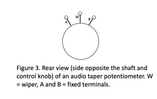
A three-terminal potentiometer (Figure 3) has two fixed terminals (labeled A and B), and a third terminal typically called a wiper (W) connected to the control knob via a rotating shaft. As the shaft turns, the wiper moves away from one fixed terminal, increasing the electrical resistance (higher resistance = less current flow) between the wiper and that terminal, while moving closer to the other terminal, which results in a decrease in resistance between the wiper and that second terminal.

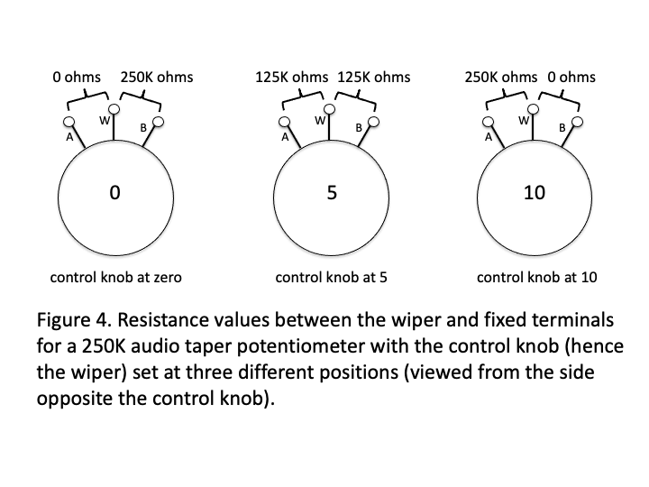
Let’s now consider a 250, 000 ohm (250K) audio taper pot, a type commonly used in guitars, with the control knob set in three different positions. As the shaft is turned to the full 10 position on the control knob (fully clockwise viewed from the front of the guitar), the physical distance between W and B is reduced and the resistance between the two terminals essentially goes to zero. An electrical signal presented at W will therefore readily flow to any device attached to the B terminal. Conversely, the resistance between W and A will be high (250K to be exact), and a signal presented to W will have difficulty flowing to any device attached to A.
In typical guitar wiring circuits, this type of pot is used for both volume and tone control (the actual ohm values of the pots vary with specific applications, although they are frequently the same for volume and control). Let’s put a couple of these 250K pots into a simple guitar wiring diagram that has one pickup, one volume control (V), and one tone control (T).
This wiring scheme is actually often used with vintage (1950s) Fender basses. (Note: In reality, the body of a pot is connected to ground. This is done in part as a convenient way to create a ground point and in part to reduce noise. In the first diagram below (Figure 5), we have not included this ground point in the interest of making it easy to visualize current flow through the circuit. In the second we have altered the diagram to illustrate the actual ground points).
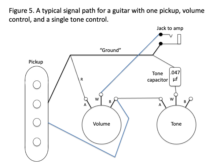

Note that this diagram includes a capacitor (labeled .047) connected to the tone control. This is the magic component of the tone circuit. If you compare this diagram with that for other guitars, for example a typical Tele or Strat, it will appear to be much simpler. In principle, however, the electrical circuit is the same. The difference is that when additional pickups are added, a selector switch for the pickups is also added, making the circuit diagram appear more complicated than it really is.
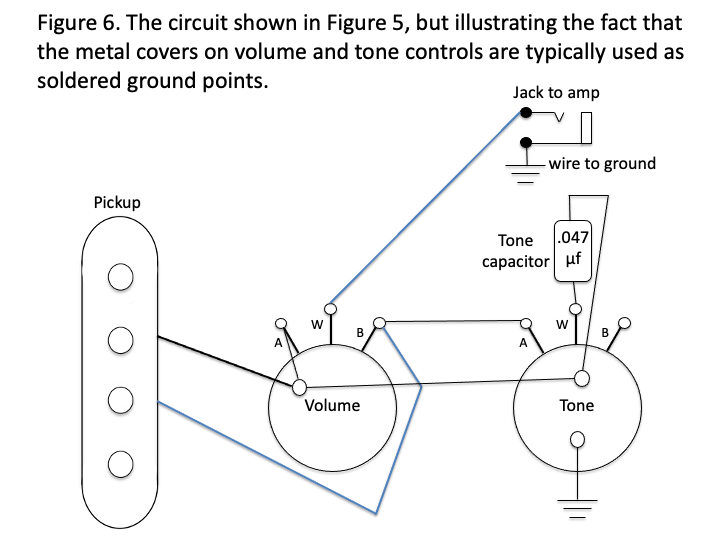
Figure 6 shows a component layout that will look more familiar to those who have studied such diagrams in the past. The signal path is identical to that shown in Figure 5. The only difference is that the outer covers of the pots have been used as ground points. This is done both for convenience and noise reduction. We have included this figure in part to drive home the fact that the wiring schemes in guitars are typically much simpler than they appear at first glance.
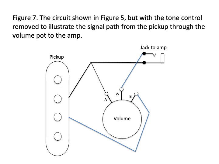
Now, let’s remove the tone control from the circuit so we can focus on how the volume control works (Figure 7). If you refer back to Figure 4, you will see that when the control knob is set at 10 (full volume), there is effectively zero resistance between the wiper (W) and terminal B, but high resistance between W and A, which means that a signal coming from the blue side of the pickup has a direct path to the amplifier with no resistance. On the other hand, if the knob is set to zero, there is high resistance between W and B, but no resistance between W and A. In this situation, the signal from the pickup is greatly attenuated between B and W. Moreover, any signal that does reach W from the B side of the pot will be thrown away because it can return to ground through the A terminal, preventing it from getting to the amp.